Converting AegisTec Dry Contacts to Signal Contacts
The AegisTec controller is designed with dry contacts (4A through 5B), which means the controller does not supply voltage to the terminals. Typically, these dry contacts are used for heaters, which provide their own 24V signal to the control. However, in some applications, you may need to convert these dry contacts into signal contacts to provide a voltage signal. An example of this is controlling an external relay or contactor to swtich a greenhouse applicance. This article will guide you through the process of converting AegisTec dry contacts to signal contacts.
(Note: This article is specifically for the AegisTec controller, not the AegisTecPlus controller.)
Step-by-Step Guide
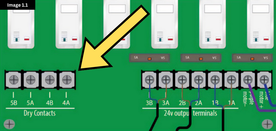
1. Identify the dry contact terminals.
Locate the dry contact terminals on your AegisTec controller. These terminals are labeled 4A, 4B, 5A, and 5B. In this article, we will assume that we are turning both 4A/4B and 5A/5B into signal contacts. See Image 1.1.
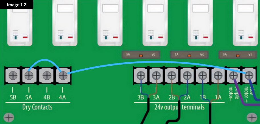
2. Connect the 24V DC internal power supply.
Run a wire from the “blue motor +” terminal to 4A and 5A, respectively (see Image 1.2 below). Contacts 4B and 5B are now no longer “dry” contacts. When the relay above the contacts engages, 24V DC will be present on 4B and 5B. (Note: 24 VDC will only show on a multimeter if the other prong of the multimeter is touching the terminal with the purple wire.)
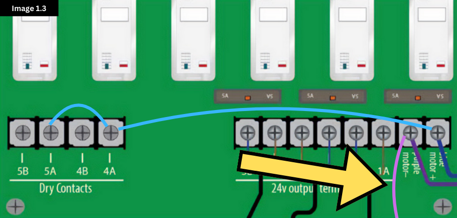
3. Connect the contacts to the device.
Usually, turning the dry contacts into signal contacts means a contactor box will be used (e.g., 42-ECO1150, Advancing Alternatives’ Contactor Box). In that case, a common wire will be connected to the “purple motor –” terminal in the AegisTec, as pictured below (Image 1.3). This wire will go to the Common terminal in the Contactor Box.
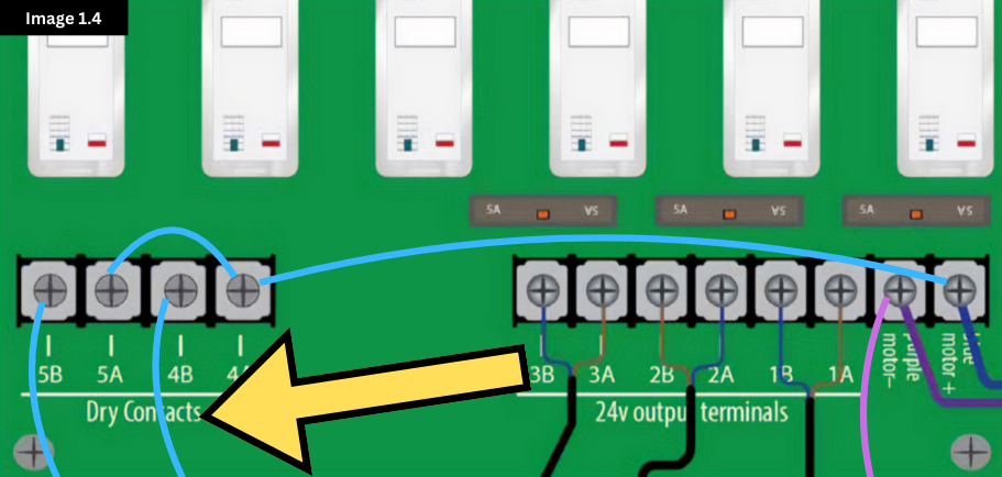
Next, the signal wires can be run from 4B and 5B. These wires will go to the input terminals in the interface box. This completes the wiring within the AegisTec. (See Image 1.4 below.)
4. Test the setup.
Activate the AegisTec controller and verify that the device is being controlled as expected. The dry contact should now function as a signal contact, providing a voltage signal to the connected device when activated.
Please note that if 4B and 5B are wired to an interface box controlling fans, you will want to go to the configuration menu on the controller and make the necessary changes. In the images above, the controller is using 1A through 3B for motors. Because the AegisTec considers 1A through 2B as one vent channel, this configuration will call for two vent channels and two fans. Fan 1 will control 4B, and Fan 2 will control 5B.
By following these steps, you can successfully convert AegisTec dry contacts into signal contacts, allowing you to control devices that require a voltage signal. If you encounter any difficulties or have further questions, please contact our support team for assistance.